![]()
![]()
This module sits on a PCB that houses a 12V to 5V regulator, the CAN transceiver board, an automatic fuse and a few other components.
My first board design came out pretty well apart from a stupid use of the wrong pins for the GPS interface (I'd used UART0 which is the one used for programming the device) and a couple of gotchas with the way the CAN-Bus and power system works on the bike.
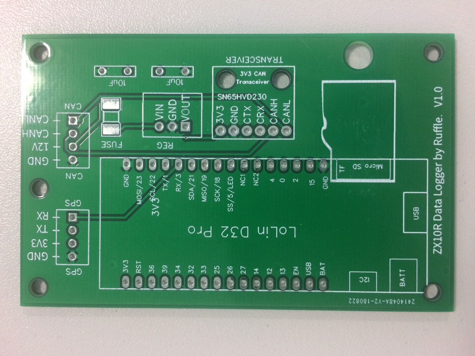
I intentionally designed the board to use 'traditional' components rather than the microscopic 'surface mount(SMD)' parts as I wanted it to be easy for someone with a normal small soldering iron to assemble. I might revisit this but for now I'll stay on this path.
The UART cockup is easily resolved by wiring the GPS TX & RX lines to a different pair of pins.
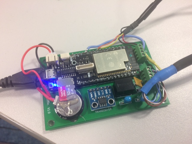
The first issue with the CAN-Bus and power was that I thought the 12V power supply on the CAN-Bus connector would be live long enough after the ignition's been switched off to cleanly close the recording file on the SDCard. There are certainly some parts of the Bike's electrical system that are still running after turning off the ignition but sadly not the 12V supply pin on the CAN-Bus connector. So I bodged on a Supercapacitor to act like a small battery supplying power just long enough to shut things down cleanly.
The second power issue is that I couldn't (can't) find a CAN-Bus signal that shows the ignition being turned off. As I was building this with both trackday riders and racers in mind and the race-loom doesn't feature an ignition switch, I needed a way of detecting the bike being powered down. This was done with a simple voltage divider from the 12V supply being monitored by a pin on the ESP32. Simple enough but it's a bit more bodgery on the PCB.
Anyway, here's an assembled V1.0 board with the requisite kludges installed.
I do have a few of these v1.0 boards available; free to anyone in the UK that wants to send me an SAE (email me: russell@lls.lls.com).
At some point I'll be doing a redesign and putting the circuit design and PCB up as a public project on EasyEDA so anyone can get a board made for a few dollars.
| Thing | Source | Price (Apr '19) |
|---|---|---|
| PCB | EasyEDA or free | £10.00 |
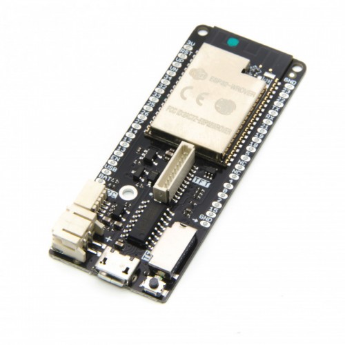
| Wemos/Lolin D32-Pro module | Wemos AliExpress Store | £11.00 |
| 1.4" TFT 128x128 LCD display (optional) | as above | £3.09 |
| 10pin SH1.0 cable for display (optional) | as above | £0.62 |
| 4pin SH1.0 I2C cable (optional) | as above | £0.62 |
| 2pin battery cable | as above | £0.24 |
| From other suppliers | ||
| GPS Receiver u-blox M8 Also available on UK EBay. Search for "UBLOX NEO-M8N GPS PX4" | Banggood.com | £16.48 |
| Automatic Resettable Fuse | RS Stock Code 712-7499 (10 pack) | £3.26 |
| Switching Regulator 8-28Vin 5V 1A | RS Stock Code 144-6290 | £2.79 |
| Ceramic Radial RCE Series 10uF 50V Capacitors (2 needed) | RS Stock Code 811-8367 (10 pack) | £13.18 |
| 2.54mm TERMI-BLOK PCB terminal block, 4P (2 needed) | RS Stock Code 909-7615 2 needed | £4.00 |
| 5.5V 4Farad Supercapacitor | Ebay | £3.24 |
| 1M and 330K resistors (one of each needed; generally sold in packs of 10) | Ebay | £2.00 |
| Sumitomo MT 090 6 Way Pin Connector (to connect to CAN-Bus socket) | Ebay | £3.99 |
| 4-core wire for CAN-Bus and, optionally, GPS extension cable | Ebay | £5.00 |
| 4-pin connector set for GPS extension cable | Ebay | £5.00 |
| 32G+ micro SD Card | Ebay | £5.00 |
| Total | £89.51 | |
The prices above are on the generous side (RS is never the cheapest) and you'll end up with a few more bits than needed. If you shopped around, the datalogger could probably be assembled for not much more than £60.